HARDWARE
Hardware
Using a Ethernet ISA card
- NE2000 compatible ISA card
The only ISA cards that are known to work are NE2000 compatible cards with an RTL8019AS controller IC.
For instance: Level One ENC-0100TB and ENC-0102T
Test the card first in a PC, you might need a DOS app to disable PnP and set the base address to 0x300. IRQs are not used. Don't solder the wires directly to the ISA card, use an old ISA connector from a 486 board instead. You only need the long slot of the ISA connector since the interface is 8 bits only. The pins are on a 0.1" grid, so you can solder it to a piece of perfboard.
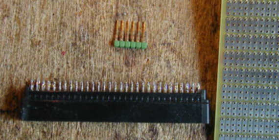
If you want to use the ISA card on a solderless breadboard, get some single row pin headers and press the pins all the way to one side. Insert next to the ISA connector and solder on the bottom.
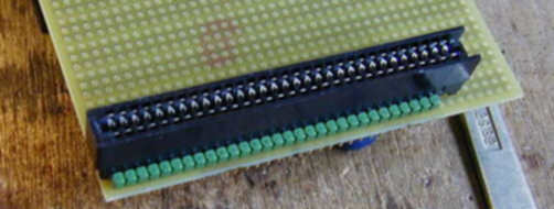
You can now press the pins in your breadboard. Remove the bracket from the ISA card if needed.
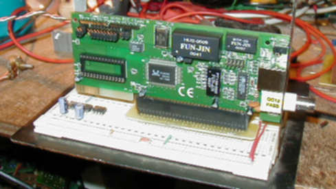
Note unused 16-bit part of ISA card floating in the air. Here is the layout of the ISA card pins and their PIC connections:
NE2000 ISA address lines:

0x0300 .. 0x031F = 0000 0011 000x xxxx
PIC pin
Signal
ISA pin
ISA pin
Signal
PIC pin
Gnd
Gnd
B1
A1
I/0 CHCHK/
isa_reset
Reset
B2
A2
SD7
isa_d7
Vcc
+5V
B3
A3
SD6
isa_d6
IRQ2/9
B4
A4
SD5
isa_d5
-5V
B5
A5
SD4
isa_d4
DRQ2
B6
A6
SD3
isa_d3
-12V
B7
A7
SD2
isa_d2
OWS/
B8
A8
SD1
isa_d1
?? (1)
+12V
B9
A9
SD0
isa_d0
Gnd
Gnd
B10
A10
I/0 CHRDY/
Vcc
SMEMW/
B11
A11
AEN
Gnd
Vcc
SMEMR/
B12
A12
SA19
Gnd
isa_iow
IOW/
B13
A13
SA18
Gnd
isa_ior
IOR/
B14
A14
SA17
Gnd
DACK3/
B15
A15
SA16
Gnd
DRQ3
B16
A16
SA15
Gnd
DACK1/
B17
A17
SA14
Gnd
DRQ1
B18
A18
SA13
Gnd
DACK0/
B19
A19
SA12
Gnd
CLK
B20
A20
SA11
Gnd
IRQ7
B21
A21
SA10
Gnd
IRQ6
B22
A22
SA9
Vcc
IRQ5
B23
A23
SA8
Vcc
IRQ4
B24
A24
SA7
Gnd
IRQ3
B25
A25
SA6
Gnd
DACK2/
B26
A26
SA5
Gnd
T/C
B27
A27
SA4
isa_a4
BALE
B28
A28
SA3
isa_a3
Vcc
+5V
B29
A29
SA2
isa_a2
OSC
B30
A30
SA1
isa_a1
Gnd
Gnd
B31
A31
SA0
isa_a0
(1) Perhaps it's needed by your card.
Seeing this table we can now assign PIC pins in netp.jal:-- Address bus: isa_a0 .. isa_a4 -- ISA address bus, low 5 bits var byte isa_addr is portb -- Data bus: isa_d0 .. isa_d7 -- ISA 8 bit data bus var byte isa_data_direction is port_d_direction var byte isa_data is portd -- Control bus: isa_iow, isa_ior -- ISA read and write strobes. Both are active low signals var bit isa_ior is pin_e0 var bit isa_iow is pin_e1 -- Control bus: isa_reset -- ISA reset signal. Active high. var bit isa_reset is pin_e2